| Lock ID | Cot1 | Patent | GB11152 |
| Maker | Cotterill | Model/Mechanism | Climax Detector |
| Keywords | Anti pick, Radial | ||
The 'Patent' menu provides a copy of the patent (No. 11,152 of 25th March 1846) for this lock and Figures 30 to 36 of the patent specification illustrate how Cotterill thought to produce his locks. This is exemplified below using a cabinet lock as an example:
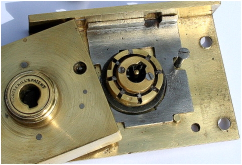
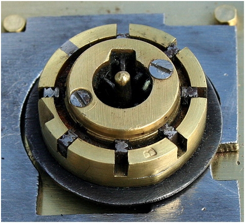
The top cap is removed to show the back plate with its steel bolt and Detector mechanism in place. The next photo below provides a close up of this mechanism. The presumed 1847 year letter "B" can be clearly seen, as are the rarely seen false notches of the sliders, projecting into the circular groove of the rotating barrel.
Also visible at about 11.00am on the barrel's dial, is a 'solid' slider, which performs two functions. Firstly, to prevent most other Cotterill keys of the same size being inserted (the deep cut required to do so would only be at the correct place in just 12 % of such keys).
The other reason may be to provide an additional point of control and tension when the cylinder is rotated, rather than using just the key bit.
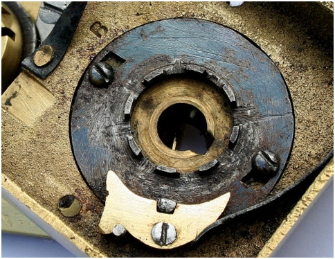
Another point of interest by the keyhole drill pin is the just visible ends of the sliders, bevelled to match the cuts in the key bit.
The next picture below shows what lies beneath the lock's top cap, a blued steel 'locking plate'. Its ridged cut-outs fit into the outer circular groove on top of the cylinder barrel (shown above), and when the key is depressed and turned to moves the sliders away, the ridged plate is released, so allowing the barrel to rotate. These projections are the equivalent of the bolt stump in a lever lock.
The brass half-moon shaped piece in that photograph is the anti-pressure device. Should tension be applied to its 'blued' locking plate, that would cause this piece to move and engage in the cut-out on the outer edge of the locking barrel; see the diagonal cut between the 8.00 and 9.00 o'clock position around the cylinder in the above photograph.
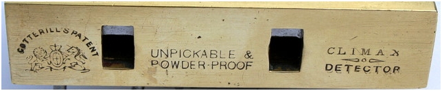
The final photograph below shows the wording on the top plate of the lock case (which unusually is bevelled downward).
These pictures are of much larger size than the actual lock size - 2.9" (7.2 cm) wide x 2.1" (5 cm) high, in order to better explain how the lock operates.