
| Lock ID | sol1 | Patent | GB1226 (1779) |
| Maker | Solomon Henry | Model/Mechanism | Drop bit |
| Keywords | warded, moveable bit, night latch | ||
Henry's Desk Lock
Henrys opinion was that the bolts of locks at the time of his patent were not sufficiently guarded. Their wards he said were too open, plain, and regular, and could be easily passed with false keys. He wanted to make the wards (upper and under) cover each other, that with an irregular ratchet serpentine ward would prevent lock pick keys from passing the wards (see Patent Drawing Figure No. 5, marked b).
The system of wards proposed in that Figure 5 was that the lock front plate had a Wheel ward at c; plus two projecting Points shown as g - in figure 6 of the patent drawing marked c); and the Ratchet and Serpentine Ward marked b. This is identified as b also in Figure 6 (the lock back plate) and opposes the Ratchet and Serpentine Ward on the front plate as shown in the photo below, to cover each other as Henry intended.
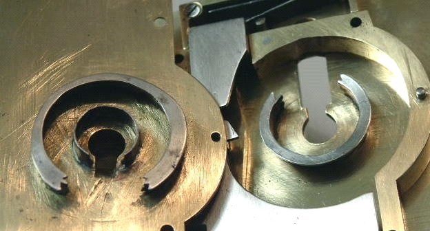
Figure 1. Internal ward system of a Solomon Henry desk lock of c. 1780. The front plate is on the left and back plate on the right with the steel bolt in the centre. Its key took the form as described below.
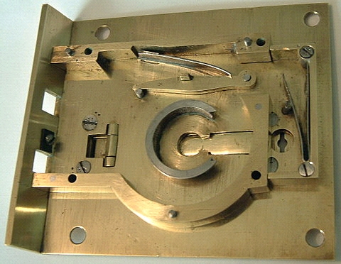
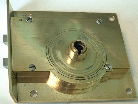
Figure 2. (left), Figure 3. (right) These views of this lock show, on the left the base with the bolt removed and on the right the front with its keyhole access.
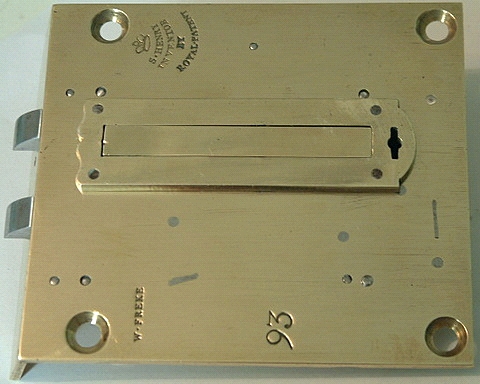
A further photograph of this fine brass drawer lock is shown below and this illustrates the spring assisted flap in the centre, onto which the key is thrust and its drop bit is lowered, enabling it to pass through the wards. However the more commonly seen style of this patent lock (albeit rarely so nevertheless) is Solomon Henrys lift-up night latch lock - photos of which are provided beneath.
Henry's Lift Up Night Latch Lock
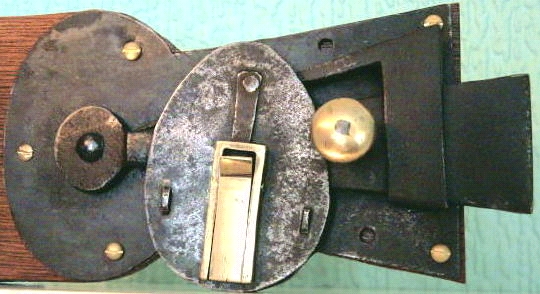
This view shows how it appears from inside the door on which it is fixed. The latch would be opened by lifting the brass knob. His patent also introduced a novel form of key as shown in the Patent Drawing Figures 8 & 10 with the Bit or Tongue of the Key swinging out of the shank as shown below
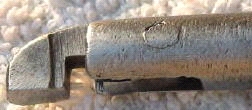
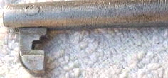
On the outside (other side) of the lock is a tubular metal pipe through which the key enters with its bit in a straight line with the shaft (above left). The sprung brass flap shown in the above photo then causes the bit to turn at right angles as the key is pressed in, above R.H. photograph. It is then in a position to pass through the internal wards. The key automatically straightens when it is pulled out to withdraw.